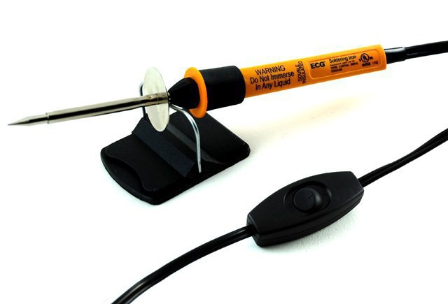
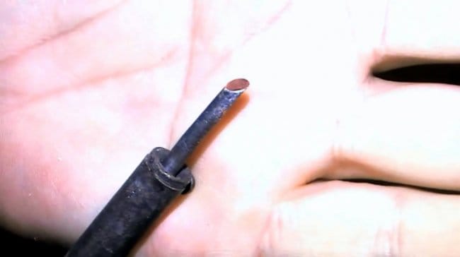
Многие отечественные паяльники производятся с медным жалом. Например, паяльники типа ЭПСН. Медное жало необходимо обработать соответствующим образом, прежде чем можно будет этим паяльником работать. Жалу нужно придать удобную для пайки форму.
Некоторые обрабатывают его простым напильником, а особенно творческие личности предпочитают отковывать его. В результате жало паяльника становится более долговечным и гораздо меньше происходит его растворение в припое в процессе пайки. Но все рано или поздно задаются вопросом о том, как залудить паяльник с медным жалом.
Особенности паяльников
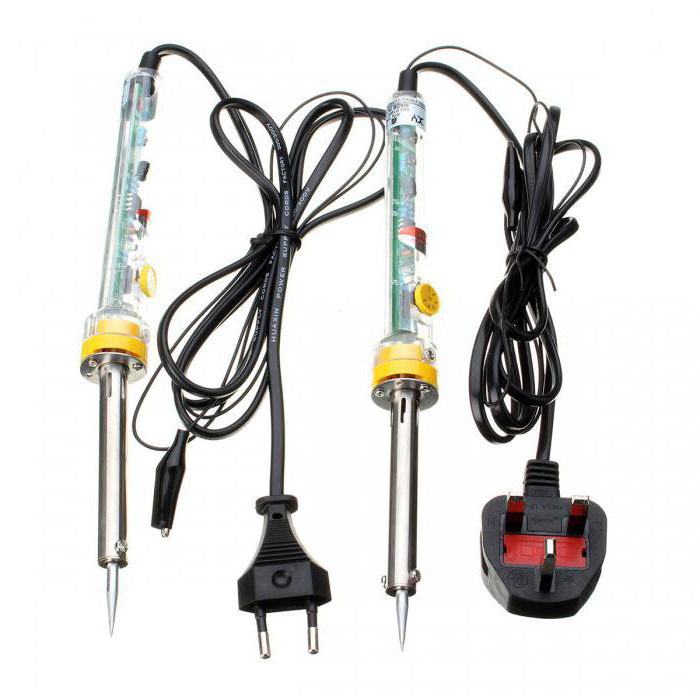
Лучше всего покупать паяльники, у которых жало крепится при помощи специального винта. Такое жало всегда можно легко вынуть и обработать его снова. Конечно, если оно прикипит в процессе использования, то этот процесс станет не таким уж легким. Поэтому, пользуясь паяльниками со съемными жалами, необходимо время от времени вынимать их и очищать место крепления, чтобы оно не прикипало.
После того как жалу придана нужная форма, его необходимо залудить. Под фразой “как залудить жало паяльника” следует понимать, что придется покрыть рабочую область жала тонким слоем припоя. Сделать это не слишком сложно. Достаточно включить паяльник в сеть, дождаться, пока он нагреется до температуры, при которой начнет плавиться канифоль, а затем обмакнуть в нее жало.
После того как паяльник будет разогрет до своей рабочей температуры, нужно ту его часть, которой производится пайка, со всех сторон покрыть припоем. Лучше для этого брать маленькие кусочки или припой, выполненый в виде проволоки. Большой кусок припоя паяльник с мощностью 25 Ватт не сможет расплавить.
Форма жала паяльника
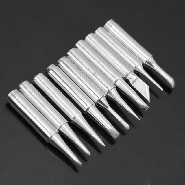
Форма жала может быть разной. Выбор зависит от привычек того, кто пользуется паяльником, и, конечно, от вида производимых с его помощью работ. Некоторым больше нравится жало паяльника в форме конуса, другим – обрезанное под 45 градусов.
Дело в том, что остро заточенным жалом паяльника можно будет паять даже транзисторы, скрытые в корпусах SOT-23, детали SMD или конденсаторы с резисторами размером 1206. Для выпаивания таких деталей из плат в больших количествах обычно применяют строительный или паяльный фен. При его отсутствии пригодится обычный паяльник с мощностью около 25 Ватт, у которого жало обработано в виде буквы П. Необходимо помнить о том, что делается это до того, как залудить жало паяльника.
Делается это для того, чтобы не перегревать выводы детали, что происходит при выпаивании паяльником с обычным жалом. А при помощи такого П-образного жала выводы выпаиваются сразу вместе, и деталь легко высвобождается из места пайки.
Лучше при выполнении работ по массовой выпайке радиодеталей использовать паяльник мощней, применяя при этом регулятор мощности. Его не так сложно изготовить самостоятельно. В таком случае подойдет паяльник с мощностью до 65 Ватт.
Довольно часты случаи, когда во время пайки вдруг начинает дымить канифоль. Это означает, что паяльник перегрет. Приходится выключать его из сети и ждать, пока он остынет. В то же время, если паяльник остывает ниже нормы, он начинает плохо паять. Используя регулятор мощности, таких проблем удается с легкостью избежать, и работать становится намного проще, а из необходимых предварительных работ не останется ничего, кроме как залудить жало паяльника.
Заточка паяльника
- Заточка жала паяльника производится напильником под углом 30-40 градусов.
- Край оставляют шириной 1 мм и слегка тупым.
- На новом паяльнике нужно только обработать мелкой наждачкой жало, чтобы удалить патину. Патина – это окись меди зеленоватого цвета.
- Если магазинная заточка не устраивает, то нужно вынуть жало и самостоятельно отковать его, придав форму вогнутой лопатки. У этого метода есть и еще один плюс – металл станет менее подвержен коррозии.
- Чтобы придать жалу законченный вид, остается обработать его напильником с мелкой насечкой.
Залудить жало – означает покрыть его тонким слоем припоя. Для этого необходимо:
- Включить паяльник и дождаться, пока медный стержень станет красновато-оранжевого оттенка. Дольше ждать не стоит, поскольку стержень может обгореть.
- Погрузить все жало в канифоль и расплавить небольшой кусок припоя.
- Покрыть припоем всю поверхность жала. Оно покроется лучше, если предварительно потереть его о деревянную поверхность.
Как залудить необгораемое жало?
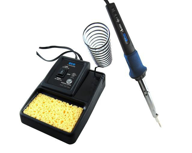
В продаже можно встретить паяльники, у которых рабочая часть покрыта специальным необгораемым составом. Этот слой очень тонкий и зачищать его, как в случае с обычным паяльником, ни в коем случае нельзя. Возникает вопрос: “Как залудить жало паяльника, если его нельзя зачищать обычным способом?” Необходимо использовать специальную губку. Подойдет и та, которой хозяйки обычно моют посуду, или кусок ткани, предварительно намоченный в воде. Пользуясь такими паяльниками, следует помнить, что любые механические воздействия существенно сокращают срок их службы.
Чтобы облудить жало такого паяльника, нужно в расплавленную канифоль опустить кусок припоя, потереть жалом по влажной ткани, удалив с него окислы, а затем поводить разогретым паяльником по припою. После лужения остается протереть тряпкой жало, и паяльник готов к работе.
При работе с любым типом паяльников следует стараться не перегревать их выше 300 градусов С, иначе придется снова заниматься лужением жала. И конечно, любой, кто пользуется паяльником, должен знать, как правильно залудить жало паяльника.
Как правильно залудить медное жало паяльника
Здравствуйте, уважаемые читатели и самоделкины!Конечно же, практически каждый из Вас весьма часто занимается пайкой. А для качественной пайки требуется содержать жало паяльника в хорошем состоянии.
Этот способ очень прост, и повторяется за несколько минут в домашних условиях.
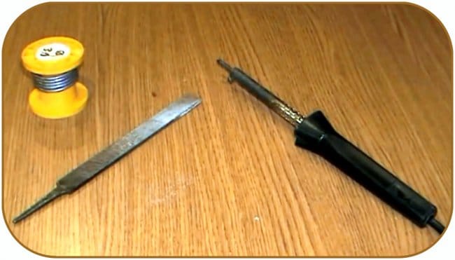
Материалы.
— Припой, канифоль
— Наждачная бумага.
Инструменты, использованные автором.
— Паяльник
— Тиски, напильник, надфиль
— Медная мочалка.
Процесс изготовления.
Этот способ годится для обычных медных жал. Современные паяльники имеют жала со специальным покрытием, и служат гораздо дольше, переточке они не подлежат. Форма самого жала может быть различной, в зависимости от Ваших задач.
Обычное медное жало со временем “выгорает”, а точнее растворяется в припое, и в нем образуется каверна. Так падает качество пайки.
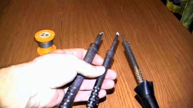
Автор продемонстрирует технику диагональной заточки.
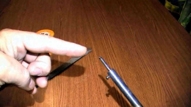
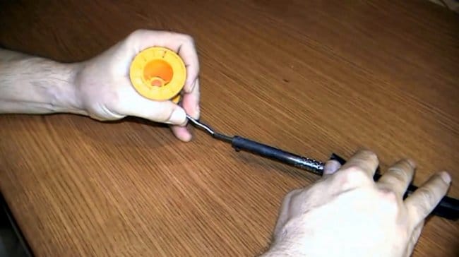
Это можно сделать вручную при помощи обычного напильника.
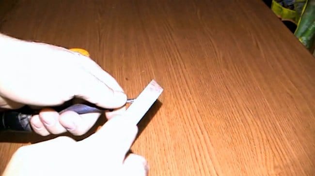
Однако лучше зафиксировать жало в тисках. Так можно получить гораздо более качественную поверхность.
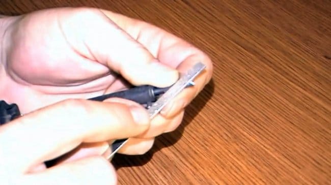
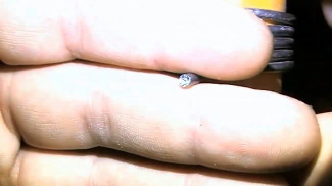
После обработки напильником образуются весьма острые грани, с которых нужно снять небольшую фаску надфилем или наждачной бумагой.
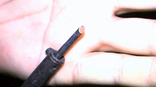
Вот так выглядит заточенный кончик жала.
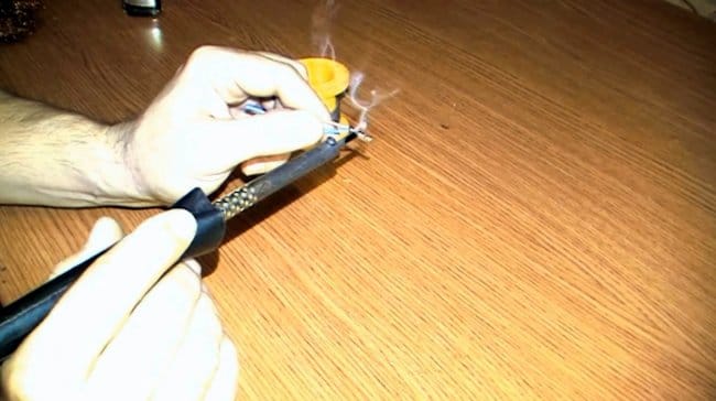
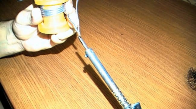
К лужению следует приступить сразу после заточки, иначе через несколько часов медная поверхность окислится, и обработку придется повторить заново.
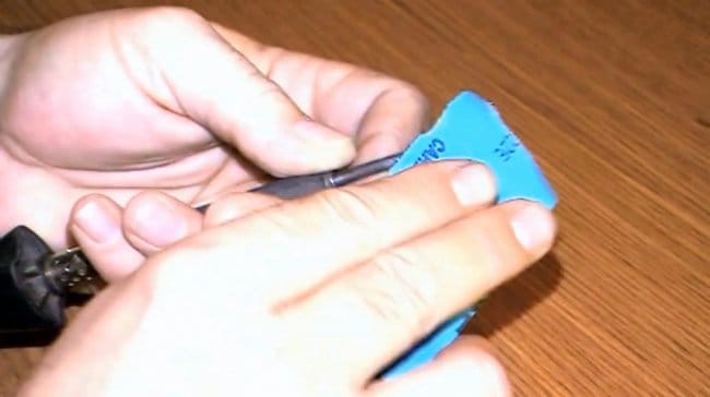
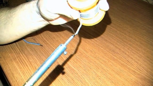
Автор использует припой в виде трубочки с канифолью внутри. Если же вы пользуетесь канифолью и припоем по отдельности, то сначала следует расплавить канифоль.
При нагреве сначала расплавится канифоль, и покроет поверхность тонким слоем, а затем расплавится сам металл. На кончике необходимо сформировать каплю из припоя, и отключить паяльник до полного остывания.
Теперь можно включать паяльник, и пайка идет отлично.
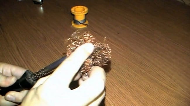
После завершения работ следует очистить кончик жала медной мочалкой, и снова сформировать на нем капельку из припоя.
Благодарю автора за простой, но полезный способ лужения жала!
Всем хорошего настроения, удачи, и интересных идей!
Авторское видео можно найти здесь.
[media=https://www.youtube.com/watch?v=-FRYcjO23nE]
Источник (Source)
В процессе работы жало паяльника постоянно нагревается, что приводит к окислению и необходимости лужения, поэтому следует знать, как залудить жало паяльника, чтобы с его помощью качественно ремонтировать бытовую технику и другие приборы.

Схема устройства паяльника.
Основные сведения о процессе лужения
Лужение паяльника – это процесс, представляющий собой покрытие поверхности стержня тонким слоем припоя, обычно для этого применяется олово. Лужение может быть как промежуточной операцией перед основной работой, так и самостоятельным действием, направленным на улучшение работы инструмента. Большинство инструментов, за исключением паяльных станций, представляет собой припой из проволоки и трубки с канифолью и нуждается в периодическом лужении. Процесс представляет собой снятие пленки окисления, которая образуется на поверхности из-за постоянного перегрева жала. Также нуждаются в лужении новые инструменты, которые еще предстоит подготовить к работе.
Общий принцип лужения одинаков: с помощью абразива жало паяльника очищается, а затем натирается до блеска. В качестве абразива могут выступать паяльник, точильный камень или наждачная бумага. Считается, что начинающим мастерам удобнее работать с напильником, но со временем каждый выбирает материал, кажущийся ему наиболее подходящим для работы.
Вернуться к оглавлению
Способы проведения лужения

Залуживание жала паяльника.
Лужение можно провести разными способами:
- с помощью абразива;
- ковкой;
- от другого паяльника.
Для лужения материал прикладывают к жалу и затачивают его до идеальной гладкости, при этом постоянно проверяя срез: он должен быть ровным. К форме жала особых требований не предъявляется. Чаще всего жалу придается форма среза, но бывают исключения – при пайке некоторых деталей удобнее делать жало конусообразной формы.
Еще один способ лужения – с помощью ковки. Этот метод позволяет увеличить срок службы острия паяльника, так как растворимость в припое будет меньше. У некоторых моделей паяльников жало бывает съемным, поэтому его лучше снять и обработать напильником.
Использующиеся в бытовых условиях паяльники не всегда мощные, обычно они бывают от 25 до 60 Вт. Электросеть, в свою очередь, не всегда обеспечивает необходимые для работы 220 В. Из-за этого возникают случаи, когда стержень паяльника не нагревается до нужной температуры и провести лужение невозможно. Проявлением этого станет припой, который будет скатываться и не сможет прилипать к поверхности металла. В этом случае для работы придется использовать трансформатор и повышать напряжение, иногда допустимо повысить его до 230 В.
Для того чтобы правильно залудить паяльник, его нужно включить и нагреть до оптимальной температуры. Оптимальный нагрев определяется очень легко – стержень паяльника приобретает красноватый цвет. Затягивать не нужно, иначе стержень может прогореть. Как только жало приобретает нужный оттенок, его тут же опускают в заранее приготовленную канифоль, вместо нее можно использовать смолу. Начнется выделение дыма. Далее расплавляют оловянный припой, стараясь, чтобы он покрывал жало равномерно.

Схема работы паяльником.
Перед тем как залудить жало паяльника таким способом, нужно запастись терпением: процедура повторяется от 3 до 5 раз, хотя количество повторов во многом зависит от состояния жала припоя и мощности паяльника. Повторив операцию в последний раз, залуженное жало прикладывают к деревянной поверхности, чтобы припой лучше распределился по поверхности стержня. Для этой процедуры применяются дощечки небольшого размера. Лучше подойдет хвойная древесина, так как в ней содержится смола, ускоряющая работу.
При работе важно соблюдать последовательность действий: сначала опускают жало в канифоль, затем прикладывают его к дощечке. Если остаются не покрытые припоем участки, последовательность повторяют. Повторять нужно столько раз, сколько понадобится для того, чтобы получился ровный слой припоя. Цвет должен быть серебристым, блестящим – это показывает, что лужение выполнено правильно. Еще один способ лужения – при помощи второго паяльника. Так как в домашнем хозяйстве редко может быть два инструмента, этот способ применяется очень редко.
Лужение по мере необходимости нужно периодически повторять.
Вернуться к оглавлению
Подготовка провода к пайке
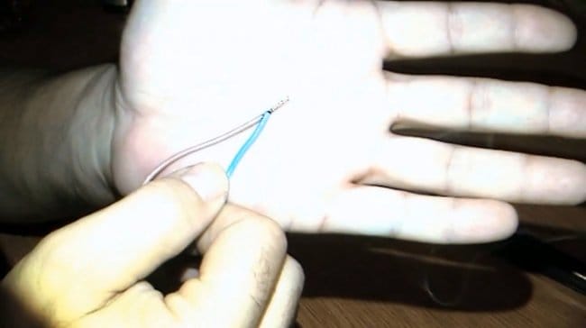
Для припаивания медных проводов их необходимо залудить таким же способом, как сам паяльник. Для работы нужно разогреть жало до рабочей температуры. Жало опускают во флюс или канифоль, потом на припой, после этого плотно прижимают провод. Все это нужно делать быстро, чтобы канифоль не успела испариться. Эту работу придется повторять несколько раз. В результате процедуры на поверхности должен получиться качественный слой припоя.
Процесс лужения окисленных деталей отличается по времени. Окислы рекомендуется сначала удалить с помощью абразивного материала. В очень трудных случаях потребуется кислота для лужения, химический состав или паяльная паста. Для пайки иногда используют проволочный припой. В этом случае необходимо опустить стержень в канифоль, затем приложить к поверхности, которую нужно залудить, а между ними поставить припой. Край припоя потереть острием жала.
Некоторые провода могут быть защищены эмалью. Чтобы удалить ее, можно обработать провод ацетилсалициловой кислотой, то есть обычным аспирином. Таблетка кладется на место и прижимается паяльником. Через некоторое время таблетка плавится и кислота воздействует на лак и разрушается. После такой простой процедуры залудить провод нетрудно.
Вернуться к оглавлению
Процесс пайки проводов
После лужения материалы полностью готовы к пайке. Они будут обеспечивать движение тока без препятствий. Процесс пайки деталей состоит из следующих основных этапов:
- Стержень нужно подвести к месту соединения, припой обволакивает части элементов.
- Канифоль обеспечивает процесс пайки, поэтому нужно опускать в нее паяльник несколько раз и только потом подносить стержень к месту соединения.
- Пайка завершается после того, как все детали оказываются в припое.
- Когда блеск припоя немного ослабевает, металл считается застывшим.
В домашних условиях часто бывает нужно паять цветные металлы, например, золото, серебро, латунь, свинец и т.д. При работе с ними обычно не возникает никаких проблем. Паять медь или сталь будет гораздо сложнее, так как эти металлы плохо поддаются лужению. Отдельные виды металлов, в число которых входит алюминий, в домашних условиях паять нельзя. Мы рассмотрели последовательность спайки деталей, но паяльник также может использоваться и для разъединения. В этом случае главный момент – правильное лужение паяльника.
Для разъединения элементов выполняются те же действия, только в обратной последовательности. Место их соединения хорошо разогревается при помощи паяльника до оптимальной температуры, несколько раз опускается в канифоль и прикладывается к соединению. К припою прикладывают острие несколько раз, пока не расплавится полностью. Затем уже детали разъединяются и обрабатываются растворителем при помощи кисточки – это позволяет убрать с них канифоль.
Вернуться к оглавлению
Несколько полезных советов
Полезные советы помогут значительно облегчить процедуру пайки деталей и лужения стержня паяльника. Самое важное – подготовить рабочее место так, чтобы поблизости была безопасная розетка и источники освещения. Материалы для лужения нужно расположить таким образом, чтобы было удобно выполнять всю последовательность действий.
Качество пайки напрямую зависит от качества лужения стержня. Поэтому важно уделять этой процедуре достаточно внимания. Но при этом существуют способы ускорить лужение. Для этого можно заменить канифоль на паяльную пасту либо специальный химический состав – флюс. Приобрести их можно в специализированных магазинах.
Подводя итог, можно сказать, что лужение – это процесс удаления с жала паяльника окисленной пленки, возникшей из-за постоянного перегрева. Лужение производится для того, чтобы улучшить точность и качество работы паяльника. Процесс проводится с помощью напильника или наждачной бумаги, в редких случаях – от другого паяльника. Качественно проведенное лужение позволяет проводить такие операции, как пайка проводов, разъединение деталей и т.д.
Как залудить паяльник? Уход за паяльником.
Подготовка и уход за паяльником
Если на эту страничку попали те, кто уже умеет правильно паять, то информация Вам вряд ли пригодится, это мануал для новичков.
Радиоэлектроника для начинающих начинается с пайки. Это аксиома. Научиться паять довольно просто, как и в любом деле, нужна практика. Если паяльный набор готов, то пора приступить к подготовке инструмента.
Заточка жала паяльника.
Прежде чем паять необходимо подготовить новый паяльник к работе, а точнее, заточить жало под определённую форму и покрыть тонким слоем припоя.

Жало необходимо заточить напильником под углом в 30-40 градусов, так, чтобы получился клин. Острый край жала следует затупить, чтобы получился плоский край шириной около 1 мм. Обычно, у новых паяльников жало уже заточено клином, но оно покрыто слоем патины – зеленоватым окислом меди и кислорода. Этот окисел надо убрать напильником по металлу или мелкозернистой шкуркой.

Кроме “классической” клиновидной формы жалу можно придать и другую, всё зависит от того, что вы будете паять. Для пайки мелких деталей можно сделать его форму наподобие вытянутого конуса с шириной края 2 – 3 мм. Или же сделать пропил в краю, чтобы можно было одним касанием выпаивать SMD-резисторы.
Сразу после того, как заточили жало, нужно установить его в паяльник и залудить. Если не сделать этого, медная поверхность жала окислиться на воздухе и его придётся затачивать заново!
Залуживаем жало паяльника.
Далее необходимо залудить жало, т.е покрыть его тонким слоем припоя. Для этого включаем электрический паяльник в сеть и ждём, когда медный стержень прогреется до определённой температуры. Когда жало прогреется, это станет заметно по красноватому оттенку, медь станет красновато-оранжевого цвета. Затягивать прогрев не стоит, иначе жало обгорит. Как только жало приобретёт чуть красноватый оттенок, его необходимо прислонить к кусковой канифоли или смоле.

При этом будет обильное выделение дыма. Расплавленной канифолью покрываем всё жало. Далее расплавляем небольшой кусочек припоя так, чтобы он равномерно растёкся по поверхности. Можно потереть жало о деревянную дощечку, так припой лучше распределиться по медной поверхности.
Медное жало должно быть покрыто ровным слоем припоя. Если на поверхности остались непокрытые припоем участки, процесс лучше заново повторить.

Вот так происходит подготовка паяльника к работе. По мере необходимости процесс надо будет повторять, но делать это часто совсем необязательно.
Писал всё довольно подробно, чтобы новичкам было как можно легче.
Уход за паяльником.
Как и любой другой инструмент, паяльник требует ухода. Время от времени жало у паяльника выгорает, на нём появляются рытвины и неровности. Устраняется выгорание затачиванием жала и его лужением. Также следует обратить внимание на то, что при длительном использовании стержень покрывается окалиной, что препятствует быстрому прогреву.

Почему жало паяльника выгорает? Дело в том, что при нагреве медь частично растворяется в припое, а сам край жала подвергается пусть и небольшому, но механическому воздействию. Также стоит понимать, что когда паяльник не используется, жало сильно разогревается и это способствует окислению меди. Поэтому при холостом простое рекомендуют либо выключить паяльник, либо уменьшить температуру. У обычного электрического паяльника типа ЭПСН температурной регулировки нет, поэтому при простое его лучше выключить.
Окалину удаляют следующим образом.
Пассатижами вытаскивают медный стержень из паяльника. Убирают окалину со стержня с помощью мелкозернистой шкурки. Можно покрыть стержень небольшим слоем графита, потерев его о грифель обычного карандаша. Это предотвратит быстрое образование окалины в будущем. Лёгким постукиванием по нагревательному элементу паяльника добиться извлечения окалины из нагревательного элемента, где был установлен медный стержень. Устанавливают медный стержень на прежнее место.

Следует время от времени проверять состояние изоляции электрического паяльника. Для этого замеряют сопротивление между сетевой вилкой паяльника и жалом. О том, как измерять сопротивление я уже рассказывал. На омметре следует выставить мегаомный предел измерения (1 – 10Мом). Помните, что касаться руками металлических щупов мультиметра при замере сопротивления нельзя. Иначе, прибор покажет общее сопротивление Вашего тела и замеряемой цепи. Прибор должен показать бесконечно большое сопротивление. Это будет свидетельством добротной изоляции между жалом паяльника и электрической сетью.
Для тех, кто уже обзавёлся паяльной станцией, подойдут сменные жала 900М из меди. Они также требуют подготовки перед работой.

Главная » Радиоэлектроника для начинающих » Текущая страница
Также Вам будет интересно узнать:
В этой короткой статье я расскажу вам, как правильно залудить паяльник.
Поскольку так сложилось, что я раньше никогда не паял, весь процесс для меня в новинку, поэтому в своем рассказе как залудить паяльник с медным жалом я буду комментировать процесс с точки зрения новичка, и это не даст мне опустить какие-то детали, которые более-менее опытному человеку кажутся очевидными, и он их просто не упомянет.
Вам понадобятся:
Если у вас прибор без цифрового контроля температуры, то постарайтесь приобрести такой. В дальнейшем вы много раз себе за это спасибо скажете.
Шаг 1: Готовим паяльник
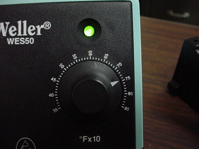
Сначала вам нужно расчистить рабочее место. Включите вилку в розетку и включите сам прибор. Смочите губку, идущую в комплекте, отожмите ее, чтобы лишняя вода стекла. Эта губка нужна, чтобы снимать об нее припой с кончика жала. Выставьте температуру на 400°С.
Шаг 2: Очищаем наконечник
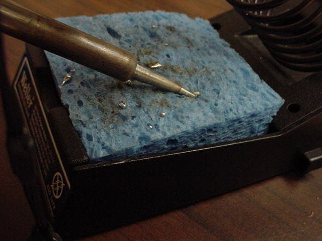
Примерно через пару минут жало нагреется достаточно, чтобы при прикосновении к губке от нее пошел пар. Если пара нет, или паяльник не лудится нужно либо еще подождать, пока паяльник греется, либо добавить воды на губку.
Когда прибор разогреется, оботрите жало о губку с двух сторон. Вам нужно убрать с него старый слой припоя.
Шаг 3: Лудим жало
Лужением называют покрытие металла тонким слоем припоя. В одну руку возьмите паяльник, а в другую – припой. Аккуратно прикоснитесь припоем к обеим сторонам жала.
Шаг 4: Цель лужения
После того, как вы залудили жало, приступайте к пайке. Паять лучше сразу после того, как вы залудили жало.
Периодически нужно повторять лужение: счищайте старый припой и наносите новый.
Лужение повышает проводимость и делает спаивание легче и быстрее, что, несомненно, является плюсом.
Некоторые радиодетали чувствительны к нагреву, поэтому их нужно паять очень быстро, чтобы не получить термического повреждения.
Также меня учили, что облудить после окончания работы нужно для продления срока службы. По прошествии некоторого времени, могу сказать, что мой паяльник все еще как новый, а прибор моего соседа, который не следует этому совету, выглядит ужасно.
90000 KSGER T12 Soldering Iron station STM32 OLED DIY Kits Solder Electric Tools Welding Iron Tips Temperature Controller Handle Case | solder electrical | soldering iron stationt12 soldering iron station 90001 90002 KSGER T12 Soldering Iron station STM32 OLED DIY Kits Solder Electric Tools Welding Iron Tips Temperature Controller Handle Case NOTE: This soldering station hasnot Hot air gun! If U want change the default Tip, please tell us or leave a message. NOTE: Iron tip do not work continuously high temperature, high temperature work is easy to damage the tip! Ordinary solder melting point is 183 ° C, lead-free solder melting point is 227 ° C, usually the welding temperature is 300-380 ° C, 380 ° C is the temperature of the dividing line, higher than 380 ° C, iron head oxidation and loss is extremely fast, seriously affect the heating core life The Higher than 380 ° C temperature display will be beating, the higher the temperature, the greater the beating! Recommended in the 300-380 ° C for welding work, most of the work can be carried out, the temperature beating is normal, does not affect the use! The soldering iron used in this soldering station is a brand new soldering iron tip.Due to the unstable resistance of the new soldering iron tip, the temperature will jump or ERROR, which is normal. After several times of use, the stability will gradually stabilize. If you mind, please do not buy. 90003 90002 Regarding the problem that the temperature displayed on the soldering station is not accurate with the actual temperature: Please use the soldering iron tip temperature tester (please do not use a multimeter) to test the temperature. When the soldering station is working at low temperature (less than 280 degrees), the temperature displayed on the soldering station and the actual temperature of the soldering iron tip are only for reference, which is not accurate because They are affected by the surrounding environment.The surrounding environment will carry away heat, causing the soldering iron tip to lose some heat. If using a HB tip thermometer, pls make sure the soldering iron tip is suspended at the center of the temperature sensing line. If you are very strict with temperature, please do not buy this soldering station. The problem that tin wire can not be melted at 227 degrees. The melting point is the melting point of the substance itself. When the temperature of the substance reaches the melting point of the substance, it is possible that the substance can not be melted.For example, the melting point and freezing point of ice are both 0 degrees Celsius, and water does not necessarily freeze at 0 degrees Celsius. Since the temperature of the substance is affected by the surrounding environment, the actual melting point of the tin wire is higher than the melting point indicated by the tin wire. If the wire is placed in a thermostat tin furnace at 226 degrees Celsius, it is possible to melt in a sealed tin furnace. If it is wrapped around the soldering iron tip, it is impossible to melt.Because there is a gap between the tin wires, and the soldering station has a temperature difference, the soldering iron will lose some heat when it heats up, and the surrounding air will also absorb heat. The melting point of lead-free wire is 227 degrees Celsius, and the room temperature is low in winter. Under the premise of calibrating the temperature of the soldering station, at least 50 degrees Celsius should be increased to offset the heat absorbed by the air, so that the heat of the wire itself can be increased to 228 degrees Celsius.About the wake of the handle Only when the soldering station is at “standby” mode, you can shake handle to wake up. When the soldering station is at “sleep” mode, you need to press the encoder to wake up. Please carefully understand the working principle of the vibration switch in the handle. The ball trigger switch built in the handle, the mounting direction of the ball switch and the rolling direction of the ball inside the ball switch need to vibrate the handle when the direction of the handle is consistent.For example, when the handle is vertical Please move the handle up and down. When swinging the handle up and down, please make sure that the ball inside the handle can trigger the SW wake-up mode, and the force needs to be slightly larger. When the handle is placed horizontally, please swing the handle left and right. Please swing the handle to an angle greater than 30 degrees, so that the ball inside the handle can trigger the SW wake-up mode. About the soldering station showing of ERROR If the ERROR is displayed, the handle or the tip is not installed properly.Please use a pair of pliers to push the tip into the innermost part of the handle. Then try rotating the tip to ensure that the tab of the tip is in good connect with the inner tab of the handle. If ERROR is still displayed and the light is always on when the tip or handle is installed, please contact us to get a solution. We encourage buyers to communicate with us to solve any problems. We will do our best for each buyer. 90003.90000 Ultimate Guide to Electronic Soldering 90001 90002 90003 90004 What is soldering? 90005 90006 90007 90004 Soldering is the joining of two metal surfaces mechanically and electrically, with the use of metal called solder (pronounced “sodder”). Solder secures the connection so it does not break loose from vibration, other mechanical forces and provides electrical continuity, so the electronic signal travels through the connection without interruption. The solder is melted using a soldering iron.Flux is used to clean and prep the surfaces, which allows the melted solder to flow (or “wet”) and bond with the metal surfaces. 90009 90005 90004 Hand soldering is the process of soldering one connection (called “solder joint”) at a time, compared to more automated soldering processes in wave soldering or reflow oven equipment. 90005 90004 90009 90005 90002 90003 What do I need to solder electronics? 90006 90007 90004 When soldering an electronic connector to a contact point (often called a “pad”), you generally need the following: 90005 90022 90023 A soldering iron capable of reaching the melting point of the solder 90024 90023 Wire solder, with or without a flux core 90024 90023 Flux if wire solder does not include a flux core or if the additional flux is needed 90024 90029 90002 90003 What is a soldering iron? 90006 90007 90004 A soldering iron is a hand tool used to solder two metal surfaces together.At its simplest form, it consists of a metal tip, a heating element that brings the tip up to soldering temperature, an insulated handle to allow safe holding of the soldering iron, and a plug for either a wall outlet or the soldering station. 90005 90004 The soldering tip’s job is to transfer heat from the heating element to the work. It has a copper interior, with is an effective and efficient thermal conductor, iron plating to protect the soft, corrosive-prone copper from flux and solder, and chrome-nickel plating to keep the flux from wetting up the tip.90005 90004 Beyond that, there are options that provide better control over the soldering iron temperature and heat response (time it takes to heat up again after soldering). Some soldering tips are metal slugs that rest against the heating element, and others are integrated with the heating element in a cartridge. 90009 90009 90009 90005 90002 90003 What is the difference between a soldering iron and a soldering station? 90006 90007 90004 On the low end, most appropriate for hobbyists, a soldering iron may plug directly into the electrical wall outlet, which provides no control over soldering iron temperature.Just on or off. With a soldering station, the soldering iron plugs into the station for greater control over temperature, and other features like set-temperature memory, lock-out, etc. 90005 90002 90003 What type of solder should I use? 90006 90007 90004 While there is a large variety of different types of solder, at the most basic, you need to choose between lead or lead-free, the diameter of the wire, flux core or solid wire, and the type of flux. 90005 90022 90023 90003 Lead or lead-free 90006 – Solder is generally a combination of metals, which are chosen for the best reliability and conductivity.Lead, often combined with tin, has been the mainstay of electronic soldering since there has been electronic soldering. Lead has a relatively low melting point and readily wets and flows, which makes the process faster, easier, and more fool-proof. Because of environmental and health concerns around lead, there has been pressure to move to lead-free solder, which is often a combination of tin and silver. Lead-free solders have a higher melting point and generally require more active or more concentrated fluxes (higher solids content) to achieve the same soldering performance as leaded solders.For typical manual soldering, if done properly, reliability should be about the same. For high-end electronics used in extreme environments (e.g. aerospace electronics), there are concerns with the tendency of bright tin to crystallize and form tin whiskers, thin wires of tin that can grow from the solder joints. 90004 If you are repairing or assembling electronics for use in the US, lead solder is the easiest to work with and provides the most reliable solder joints. The lower heat also generates less thermal stress on the rest of the PCB.If the end product is being shipped outside of the US, especially to Europe, you should consider lead-free solder. An exception might be for high-reliability electronics like used in aerospace. In that case, check with the specifications and requirements of the end-user of the electronics. Lead-free may still be required, or there may be exemptions in place that allow for the use of lead solder. 90005 90024 90023 90003 Diameter of solder wire 90006 – Make sure you do not confuse solder wire intended for plumbing with electronics solder wire.Wire for plumbing will be much thicker, 2mm diameter or higher. Electronics solder wire will be thinner, 1.5mm or smaller, down to 1 / 2mm or less. Match the diameter to the size of the connectors and contacts you are soldering. Too small and you will be going through too much solder, and too large could be hard to maneuver around a dense PCB, and could increase the chance of thermally stressing or even soldering other components that are unrelated to your repair. 90024 90023 90003 Flux core or solid wire 90006 – Most wire solder comes with a flux core, so the flux automatically activates and flows over the soldering area when the solder is melted.It is more convenient and efficient to work with. Solid wire can be used, with flux added with a brush, a bottle dispenser, or a pen dispenser. Unless a very specific flux is required that is not available as a wire solder core, flux core wire solder is generally recommended. 90024 90023 90003 Type of flux 90006 – No-clean flux is a good choice for soldering where cleaning is to be avoided. The light residue can be left on the board, or removed with a flux remover. Rosin activated flux (RA) provide excellent solderability in a wide variety of applications.It is best to remove the residue after soldering for aesthetics and avoid corrosion down-the-line. Rosin flux (R) or mildly activated rosin flux (RMA) can generally be left on the PCB after soldering unless the aesthetics are a problem. Water soluble flux (OA) is a very active flux engineered to be removed easily with DI water, like in a batch or in-line system. It can also be removed with isopropyl alcohol (IPA). It is very important to clean off water soluble flux residues because they are highly corrosive.90004 You may also see options for “halogen-free” or “zero halogen”. This is for companies that have green initiatives, or have to comply with halogen restrictions due to regulatory or customer restrictions. Halogens include chlorine, fluorine, iodine, bromine and astatine elements. These can come with trade-offs like cleanability, so if you are not required to eliminate halogens from your process, it is easier to stay with standard fluxes with halogens. 90005 90024 90029 90009 90002 90003 Should I use lead or lead-free solder? 90006 90007 90004 If you are repairing or assembling electronics for use in the US, lead solder is the easiest to work with and provides the most reliable solder joints.The lower heat also generates less thermal stress on the rest of the PCB. If the end product is being shipped outside of the US, especially to Europe, you should consider lead-free solder. An exception might be for high-reliability electronics like used in aerospace. In that case, check with the specifications and requirements of the end-user of the electronics. Lead-free may still be required, or there may be exemptions in place that allow for the use of lead solder. 90005 90002 What is flux? 90007 90004 Think of flux and a prepping agent for the soldering process.When joining two metal surfaces together with solder, there needs to be a good metallurgic bond, so the solder joint does not break loose or electrical continuity fluctuate with mechanical, temperature and other stresses. Flux removes any oxidization that may be present and slightly etches the surface to promote wetting. “Wetting” is the process of solder flowing over the surface of the contacts and soldering tip, which is very important in the soldering process. 90005 90002 90003 What type of flux should I use? 90006 90007 90004 No-clean flux is a good choice for soldering where cleaning is to be avoided.The light residue can be left on the board, or removed with a flux remover. Rosin activated flux (RA) provide excellent solderability in a wide variety of applications. It is best to remove the residue after soldering for aesthetics and avoid corrosion down-the-line. Rosin flux (R) or mildly activated rosin flux (RMA) can generally be left on the PCB after soldering unless the aesthetics are a problem. Water soluble flux (OA) is a very active flux engineered to be removed easily with DI water, like in a batch or in-line system.It can also be removed with isopropyl alcohol (IPA). It is very important to clean off water soluble flux residues because they are highly corrosive. 90005 90004 You may also see options for “halogen-free” or “zero halogens”. This is for companies that have green initiatives, or have to comply with halogen restrictions due to regulatory or customer restrictions. Halogens include chlorine, fluorine, iodine, bromine and astatine elements. These can come with trade-offs like cleanability, so if you are not required to eliminate halogens from your process, it is easier to stay with standard fluxes with halogens.90005 90002 90003 Do I need to add extra flux when soldering? 90004 90009 90005 90006 90007 90004 If soldering a simple connection, like 2 wires, or a thru-hole lead, the flux in a flux core solder should be enough. For more complex soldering techniques, like drag soldering multiple leads on a surface mount component, additional flux may need to be added. The flux is activated and consumed when it originally flows from the core. If the solder is worked further, like when you drag across multiple leads, you run the risk of cold joints or bridging without additional flux.While more seems like it should be better, take care not to over apply flux. Excess flux needs to be removed, especially if it is not fully activated by being heated to full soldering temperature. 90005 90004 Associated products: 90005 90002 90003 How do I apply extra flux? 90006 90007 90004 Flux can be painted on with an acid brush, applied with a needle bottle dispenser, or with a pen dispenser. While more seems like it should be better, take care not to over apply flux. Excess flux needs to be removed, especially if it is not fully activated by being heated to full soldering temperature.90005 90004 Associated products: 90005 90002 90003 How do I solder? 90006 90007 90119 90023 Make sure the surfaces to be soldered are clean. 90024 90023 Turn on the soldering iron and set temperature above the melting point of your solder. 600 ° -650 ° F (316 ° -343 ° C) is a good place to start for lead-based solder and 650 ° -700 ° F (343 ° -371 ° C) for lead-free solder. 90024 90023 Hold the tip against both the lead and contact point / pad for a few seconds. The idea is to bring both up to a soldering temperature at the same time.90024 90023 Touch the solder wire to the lead and contact point / pad a few times until solder flows around the lead and contact. 90024 90023 Inspect the solder joint to make sure there is full coverage over the contact area and lead. If it is a thru-hole lead, the hole should be filled and the solder joints a slight pyramid shape. 90024 90023 If necessary, trim the lead with a shear lead cutter. Do not trim into the solder joint, which can damage the connection. 90024 90023 If using rosin activated flux, aqueous flux, or if the aesthetics of the flux residue is a problem, clean the area with a flux remover.90024 90134 90004 Associated products: 90005 90002 90003 How hot do I set the solder iron? 90006 90007 90004 600 ° -650 ° F (316 ° -343 ° C) is a good place to start for lead-based solder and 650 ° -700 ° F (343 ° -371 ° C) for lead-free solder. You want the tip hot enough to melt the solder efficiency, but excess heat can damage components as the heat travels along the leads, and it will reduce the life of the soldering tip. 90005 90002 90003 How do I tell a good solder joint from a bad one? 90006 90007 90004 Inspect the solder joint to make sure there is full coverage over the contact area and lead.Some things to watch out for: 90005 90022 90023 If it is a thru-hole lead, the hole should be filled and the solder joints a slight pyramid shape. 90024 90023 If a surface mounts solder joint, the solder should fully cover the contact pad and surround the lead. 90024 90023 The lead should not be loose or wiggle once it is soldered. 90024 90023 The solder should not overflow or bridge onto other contact points / pads. 90024 90023 If using lead-based solder, the solder joint should be shiny.Unfortunately, lead-free tends to have a duller finish, so not a good indicator in that case. 90024 90029 90002 90003 How do I select the best soldering tip for my PCB repair job? 90004 90009 90005 90006 90007 90004 The goal is to match the tip shape and size to the contact pad. That allows you to maximize the contact surface area, so you heat the lead and contact area as quickly as possible. If you choose a tip that is too large, you have more tip volume to heat, which will slow down the heat recovery, the time it takes for the tip to reheat after soldering a joint.It also runs the risk of interfering with other components and contact areas. If you choose a tip that is too small, you will not have enough surface area of the tip in contact with the lead and contact area to transfer heat efficiently. It will take more dwell time, which slows you down and could increase the thermal stress of the component. 90005 90004 Make sure you are using a soldering iron and tips intended for electronic PCB soldering. Tips intended for other applications, like stained glass, plumbing, or heavy electrical work, are generally much larger than what is appropriate for electronics.90005 90004 Soldering tips come in all kinds of shapes to facilitate different PCB geometries: 90005 90022 90023 90003 Pointed or conical 90006 – The end of the soldering tip comes to either a point or around the flat area. The size is specified by the diameter of the end, so can be as small as 0.1mm or larger than 1mm. These tips are generally used when pin-point accuracy is needed, like with very fine leadless surface mount components. They may be long for greater reach in dense board design, or a shorter microtip to reduce the amount of tip metal that needs to be heated.This can improve heat recovery. The ends of the tips may also be bent to avoid interfering with other components or contact areas. 90024 90023 90003 Blade or knife 90006 – A blade tip is usually used for drag soldering when the solder is drawn across multiple contact pads. This is common when soldering surface mount technology (SMT) components. The size is measured along the length of the blade and can be 6.3mm (1/4 “) or larger. 90024 90023 90003 Chisel or screwdriver 90006 – A chisel allows you to heat a larger contact area, so useful for thru-hole solder joints.Lengths may vary and can also be bent, like with a conical tip. The size is mainly specified as the length of the flat area, but the depth or thickness of the tip may also vary. These can be so small they almost look like a point, like under 1mm, and as wide as 5 or 6mm. 90024 90023 90003 Bevel 90006 – A beveled tip has a flat oval end set at an angle. Picture a metal rod that is a cross section at an angle. The size is specified by the diameter of the “rod” or shaft and sometimes the angle of the bevel.A bevel can be as small as 1mm or 4mm or larger. 90024 90023 90003 Flow tips 90006 – A flow tip looks similar in design as a beveled tip, but instead of a flat area, it is a little indention or cup. This is also called a “mini-wave tip”, and is commonly used for drag soldering, as explained above. 90024 90029 90004 Associated products: 90005 90002 Is it ok to set the heat at maximum temperature to speed up soldering? 90007 In soldering, like everything else, speed is king. Operators will turn up the soldering temperature to speed up heat throughput.This allows them to go from one solder joint to the next faster. The catch – the higher the heat, the shorter the tip life. Sure, solder stations may go up to 900 ° F, but 750 ° F is the highest you need to go for a lead-free wire. The extra heat can also unnecessarily stress components, increasing the chances of PCB failure later. 90002 90003 Why is the solder dripping off the soldering tip? 90006 90007 90004 That is an indication that the soldering tip needs to be cleaned, so it is a “cold” tip (although it is still very hot, so do not touch!).When flux and oxidation build up over time, the heat does not transfer as effectively and the solder does not wet, or flow over the tip properly. The solder will tend to melt but just drip off the tip. This makes it difficult to move to solder around contact areas the way you may need it. 90005 90002 90003 How to clean a soldering iron? 90009 90009 90006 90007 90004 Solder stations normally come with a sponge and / or brass “brillo” pad. The purpose is to remove excess flux and solder from the tip.If too much flux builds up and burns onto the soldering tip, it will eventually dewet and be unusable (but not necessarily unrecoverable). Unless the tip cleaning tools are used properly, they can do more harm than good. When choosing a sponge, make sure it is made of natural cellulose (like Plato replacement sponges). Synthetic sponges will melt onto the soldering tip and can shorten tip life. Use clean DI water. Tap water may include minerals that can build-up on the tip. When you saturate the sponge, wring it out so it is not dripping wet.Too much water can increase the thermal stress of the tip, and slow down tip recovery. 90009 90009 90005 90004 When the soldering tip has turned black from baked on fluxes and no longer wets properly, it is time for the cleaning tools of last resort. Tip tinner (Plato # TT-95) is a combination of lead-free solder and cleaner. While the soldering iron is at full temperature, roll it in the tip tinner. As you roll it, it should change from black to shiny silver as the baked flux is cleaned off.Then wipe off the excess tip tinner from the soldering tip, and retin using wire solder. Do not let the name fool you – “tip tinner” is not intended to be left on the tip. 90005 90004 Polishing bars are also available and used to scrub the tip clean of flux residues. This should only be used as a last resort because you will be removing iron along with the burnt flux. Once a tip shows pitting, actual holes in the iron, it is time to be replaced. 90005 90004 Associated products: 90005 90002 90003 Is a brass “brillo pad” or sponge better for cleaning soldering tips? 90006 90007 90004 Like everything else, there are pros and cons to each: 90005 90002 90003 Brass Tip Cleaner 90004 90005 90006 90007 90022 90023 Pro-Fast and easy to use, does not require saturating with water, and does not thermally shock the soldering tip.90024 90023 Con – It is abrasive, although brass is softer than the iron on the end of the tip. It has more of a tendency to scratch the chrome plating, which keeps the solder from wetting up the tip. That could allow corrosion to creep in under the plating, reducing the life of the tip. 90024 90029 90004 Remember to use a jabbing motion using a brass tip cleaner. Wiping across the surface increases the likelihood of flinging molten solder. 90005 90002 90003 Cellulose Sponge 90009 90009 90006 90007 90022 90023 Pro – It is an effective and fast way to clean a tip.They come with different holes or slits to make it even faster and easier, and to avoid flinging molten solder. 90024 90023 Con – Cools down the tip, so requires the tip to heat up again. It also can thermally shock the tip, especially if the sponge is overly saturated. This can shorten the tip life by creating micro-fractures in the iron plating. 90024 90029 Make sure you are using a cellulose sponge that is intended for cleaning soldering tips. Cellulose is a natural material derived from wood pulp.It will not melt and damage the soldering tip as a synthetic sponge would. The sponge should not be soaking wet, just lightly damp. Wring it out thoroughly after saturating with Deionized (DI) water. DI water is recommended to prevent mineral build-up on the soldering tip. Once your soldering tip has been cleaned, remember to retin by melting on a small amount of solder on the end of the tip. This prevents the working end of the tip, which is iron, from corroding when exposed to air over a period of time.Associated products: 90002 90003 Should I clean all the solder off the soldering tip after I’m finished soldering? 90006 90007 It is a common practice to wipe down the soldering tip before putting it back into its holder. This exposes the raw iron on the working end of the tip, which will rust in the open air. Add any residual flux to the mix, and you have a prematurely pitted soldering tip. Before taking a break or stopping for the day, wipe off residual flux and solder, and retin by applying fresh solder to the end of the tip.90002 90003 What can I do to increase soldering tip life? 90006 90007 90004 Since the move from lead to lead-free solders, a common complaint has been short tip life. The higher heat needed for lead-free solders and flux with greater activity all leads to faster tip burn-out. Often the tips turn black, and the solder beads and just drips off the end of the tip. It may also be referred to as a “cold tip”, but take care not to touch it with your bare fingers! 90005 90004 Soldering tips have a copper core that transfers heat from the heating element to the working end (tip of the tip).Because copper is very soft and easily corroded and worn away, other metals are used to plate over the copper, including an outer layer of iron. Although iron is very hard, it will still corrode eventually. In addition, it can be coated with flux and other soils, which can cause dewetting. Corrosion and dewetting will slow down soldering and eventually necessitate scrapping the tip. Although all tips will have their day in the trash bin, there are several steps an operator can take to increase tip life: 90005 90119 90023 Turn down the heat 90024 90023 Properly clean the tip 90024 90023 Tin the soldering tip 90024 90023 Use special cleaning tools 90024 90134 90004 When leaving the solder station for anything over 5 minutes, turn off it off.When you leave the station turned on, the tip remains at soldering temperature, further reducing tip life. Modern soldering equipment heats up to a soldering temperature in seconds, so the time savings is not worth the reduction in tip life. 90005 90004 Associated products: 90005 90002 When should I throw away an old soldering tip? 90007 90004 When the tip is black and dewetting (solder does not cling to it), called a “cold tip”, it can generally be cleaned and used again. Once there is pitting and visible corrosion, it is time for a new tip.The outside of a soldering tip is plated with iron over the thermally conductive copper center. This protects the soft, corrosion-prone copper from the harsh fluxes. Once flux gets through the iron plating through pits, the tip will be eaten away quickly. 90005 90002 90003 How can I avoid corrosion on the PCB after I’m finished soldering? 90006 90007 90004 Flux residues can cause dendritic growth and corrosion on PCB assemblies, so make sure you’re using best practices and clean the board.After all, the components have been replaced and excess solder removed … 90005 90022 90023 Clean the area thoroughly with a quality flux remover. 90024 90023 Angle the board to allow the cleaner and residues to run off. 90024 90023 If needed, use a horsehair brush or lint-free wipe to gently scrub the PCB, and then follow with a rinse. 90024 90023 If using a wipe, make sure it does not leave fibers / lint on your PCB, which may cause issues later. 90024 90029 90004 This is an optional step for no-clean flux, but still a good idea for densely populated or high voltage boards.It is absolutely required, regardless of the flux type, if you plan to follow your repair with conformal coating. 90005 90004 Associated products: 90005 90002 90007 90002 90003 10 tips to good soldering 90006 90007 90119 90023 Start with a clean surface. 90024 90023 Match the size of your wire solder to what you are soldering. 90024 90023 Match your soldering tip to what you are soldering. 90024 90023 Select your solder and flux carefully. 90024 90023 Keep your tip clean and tinned.90024 90023 Select a soldering temperature that is hot enough to efficiently melt the solder, but not too hot. 90024 90023 Hold the soldering tip to the lead and contact point / pad until both are brought up to temperature. 90024 90023 Apply enough solder to cover the contact pad and surround the lead. 90024 90023 If necessary, trim your leads with a sharp shear lead cutter, and do not trim into the solder joint. 90024 90023 Clean flux residues from the soldering area with a quality flux remover.90024 90134 90004 Associated products: 90005 .